
 Español
 Deutsch

How To Select Pneumatic Air Shaft For Different Core Sizes
Core size has a direct influence on how a winding shaft engages with a roll core. The inner diameter of the core determines how much space is available for the shaft's expanding components, while the core wall provides the surface against which the holding force is applied.
A suitable match allows the shaft to support the core without creating unnecessary deformation. When the fit is poorly matched, several operating problems can appear. The roll may shift during rotation, loading can become less convenient, and the material being wound may develop alignment issues.
Core dimensions also vary according to the type of material being processed. A flexible paper core may react differently from a rigid plastic core, even when both have a similar internal opening. The shaft selection process consequently needs to consider more than the nominal core diameter.
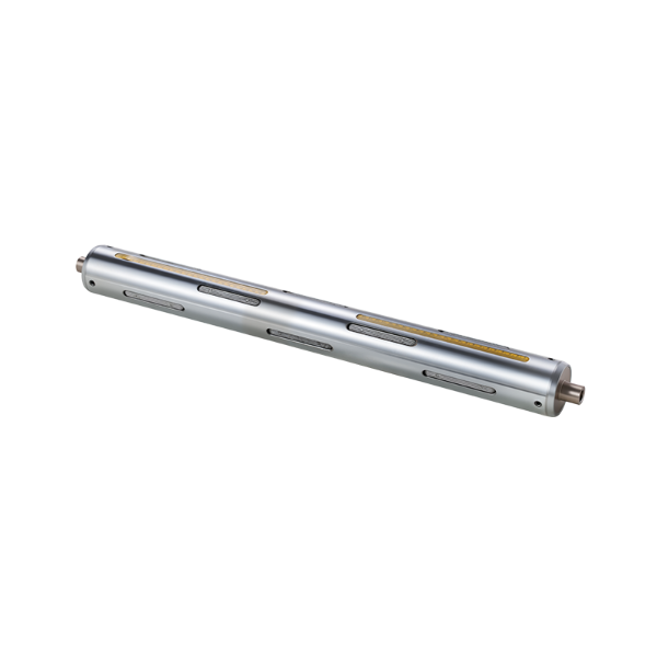
A Pneumatic Air Shaft uses compressed air to change the position of its gripping elements. In the released state, the components remain sufficiently retracted for the core to be placed onto the shaft. Once air is introduced, the gripping elements move outward and contact the inside surface of the core.
Several factors are worth checking before selecting a shaft:
- Internal core diameter
- Core wall condition
- Core material and rigidity
- Roll width
- Roll weight
- Available mounting space
- Loading and unloading method
The relationship between shaft and core becomes particularly important when one production line handles different roll formats. A shaft designed around one core dimension may not provide the same operating behavior with another size.
Core fit also affects maintenance. Excessive contact pressure can accelerate wear around the gripping area, while insufficient engagement can cause repeated movement between the shaft and core. Matching the shaft configuration to the actual working conditions helps reduce unnecessary mechanical stress.
How Does a Pneumatic Air Shaft Work With Different Cores
The operating principle is based on controlled expansion and release. Air enters the internal mechanism and creates movement in the gripping elements. These elements extend toward the inner wall of the roll core and establish contact during winding or unwinding.
When the air supply is released, the gripping parts return toward their resting position. The core can then be removed without requiring the entire assembly to be dismantled.
Different core diameters change the position at which the gripping elements meet the inner wall. A smaller opening leaves less internal space, while a larger opening requires the expansion system to cover a wider distance before stable contact is established.
The contact area matters as much as the movement itself. A shaft needs to hold the core firmly while avoiding unnecessary concentration of force in a small section. Core deformation can become a concern when the wall is thin, soft, or already damaged.
During operation, several conditions can indicate whether the shaft and core are working together properly:
- The core remains positioned during rotation
- Expansion occurs without irregular movement
- Release is smooth after air is removed
- The core does not show excessive local deformation
- The winding material remains aligned with the equipment
Air pressure influences how firmly the gripping elements engage with the core. The appropriate setting depends on the core structure, roll condition, and equipment arrangement. A pressure level suitable for a rigid core may not produce the same result with a softer material.
The shaft therefore functions as part of a wider winding system rather than as an isolated component. Core structure, air supply, roll movement, and machine alignment all affect the final operating condition.
Which Core Sizes Require Different Shaft Configurations
Different core sizes can require different shaft arrangements because the expansion range, gripping position, and available internal space are not identical.
Small internal openings generally leave limited room around the shaft body. Compact gripping components may be needed to enter the core without interfering with the inner wall. Larger openings provide additional space but may require an expansion arrangement capable of reaching the core surface securely.
The core wall itself adds another consideration. A rigid wall can tolerate a concentrated contact force differently from a softer wall. When the core is prone to deformation, the gripping arrangement needs to distribute contact more carefully.
Multiple core sizes within the same production environment can create a separate selection challenge. Changing between cores may require a different shaft configuration, an adjustable arrangement, or a production setup designed around compatible dimensions.
| Core Condition | Shaft Selection Focus | Operating Concern |
|---|---|---|
| Narrow Internal Opening | Compact gripping structure | Clearance during loading |
| Wide Internal Opening | Suitable expansion range | Stable internal contact |
| Rigid Core Wall | Consistent gripping force | Secure positioning |
| Flexible Core Wall | Controlled contact | Local deformation |
| Mixed Core Sizes | Adaptable configuration | Changeover convenience |
Core length should also be considered. A shaft needs to fit the equipment while providing suitable support across the roll structure. An arrangement that extends beyond the available machine space can interfere with loading or nearby components.
Roll width introduces another practical factor. Wider rolls can place different mechanical demands on the shaft and supporting equipment. The shaft configuration should correspond with the actual position and distribution of the roll rather than being selected only from the core opening.
For production environments handling varied materials, documenting the commonly used core dimensions can make shaft selection more consistent. Internal diameter, wall condition, material type, and roll arrangement provide useful reference points when comparing configurations.
What Should Be Checked Before Choosing the Shaft
Selection begins with the physical conditions of the winding application. Core dimensions should be checked directly rather than estimated from general product descriptions. Small variations in the inner opening can affect how the gripping components engage.
The condition of the core also deserves attention. Crushed edges, uneven inner walls, or previous mechanical damage can change the contact between shaft and core. A technically compatible size may still perform poorly when the core itself is distorted.
Machine installation space is another key consideration. Shaft length, mounting position, surrounding components, and loading direction all influence whether a particular configuration can be integrated into the equipment.
The roll material provides additional context. Films, papers, foils, textiles, and other wound materials can respond differently to changes in tension and alignment. The shaft needs to maintain a stable core position without introducing unnecessary movement into the roll.
Before making a selection, the following information can be organized:
- Actual core opening and wall condition
- Core material
- Roll dimensions and loading direction
- Shaft mounting arrangement
- Available clearance around the shaft
- Required expansion and release behavior
- Typical operating environment
Communication with an Air Shaft Factory can also focus on these practical details rather than relying only on a shaft name or general category. Clear information about the core and equipment allows the shaft configuration to be considered in relation to the actual application.
A careful selection process also leaves room for future production changes. When several core formats may be used on the same equipment, compatibility should be considered during the initial configuration rather than treated as a later adjustment.
The connection between core size and shaft design becomes clearer when the physical fit, gripping movement, machine space, and roll condition are viewed together. Such details provide the foundation for choosing an arrangement that can operate consistently within the intended winding process.
How Does Core Material Affect Air Shaft Selection
Core material influences how the shaft interacts with the inner wall during winding. Different materials have different levels of rigidity, surface friction, and resistance to local pressure. A suitable shaft configuration needs to account for these differences rather than relying on internal diameter alone.
Paper cores can respond to gripping pressure differently from plastic or composite cores. A rigid core may maintain its shape during clamping, while a softer structure can deform around the contact points. Excessive local pressure may leave marks or change the circular shape of the opening.
The condition of the inner wall also matters. A smooth surface can create a different contact relationship from a rough or uneven one. Damaged sections may reduce the consistency of the grip, particularly when the roll experiences repeated acceleration or deceleration.
Core construction should be checked alongside the material itself. Important points include:
- Wall rigidity
- Inner surface condition
- Resistance to deformation
- Core edge condition
- Surface cleanliness
- Compatibility with the gripping method
A lightweight core may require controlled engagement to avoid distortion. A heavier or more rigid core can place greater mechanical demand on the shaft and its supporting structure.
Core material can also affect loading and unloading. Some cores slide easily into position, while others require more careful alignment. A shaft that allows smooth release can reduce handling difficulty when the production setup involves frequent roll changes.
The relationship between the core and the gripping elements remains important after installation. During rotation, uneven contact can cause movement between the shaft and core. Such movement may affect roll alignment and create additional wear at the contact points.
How Can Air Pressure Affect Different Core Applications
Air pressure controls the movement of the gripping elements inside the shaft. As pressure changes, the expansion and release behavior can also change, making pressure adjustment an important part of operating preparation.
Insufficient pressure may leave the gripping components with limited contact against the core. The roll can then shift during rotation, particularly when winding tension changes.
Excessive pressure creates a different concern. A rigid core may tolerate greater contact force, while a softer wall can become compressed or distorted. Repeated pressure at the same contact points may also affect the condition of the core opening.
Pressure should be considered together with core material, roll condition, and shaft structure. A setting suitable for one production arrangement does not automatically suit another.
During operation, several signs can help identify an unsuitable pressure condition:
- Irregular core movement
- Visible deformation around contact areas
- Difficulty releasing the core
- Uneven roll alignment
- Changes in winding stability
The air supply itself also needs attention. Leaks, unstable connections, or restricted airflow can change the response of the gripping mechanism. Regular inspection of air-related components can help maintain consistent expansion and release.
Adjustment should take place under controlled operating conditions. A test run with the actual core type can reveal how the shaft behaves before regular production begins. Core condition should remain part of the evaluation because damaged or weakened cores may react differently from intact ones.
What Role Does an Air Shaft Factory Play in Shaft Configuration
Shaft configuration is closely connected with the equipment in which the component will operate. Core diameter, shaft length, mounting position, roll width, and loading direction can all influence the final arrangement.
An Air Shaft Factory may need application information before determining a suitable configuration. A general description such as “large core” or “heavy roll” does not provide enough detail to assess how the gripping structure should interact with the equipment.
Useful information can include:
- Core internal diameter
- Core material and wall condition
- Roll dimensions
- Machine mounting structure
- Shaft insertion direction
- Space around the shaft
- Expected loading and unloading process
Manufacturing considerations extend beyond the external shaft body. Internal gripping components, air passages, supporting sections, and connection areas need to work as one assembly.
Different machine layouts can also require different shaft lengths or mounting arrangements. A configuration that fits one winding machine may not suit another because surrounding structures and installation clearances can vary.
When several core sizes are used, the configuration discussion can include changeover requirements. An adjustable structure may be appropriate in some production settings, while a dedicated arrangement may suit equipment that handles a narrow range of core formats.
Clear technical communication can reduce avoidable mismatches during manufacturing and installation. Drawings, core samples, equipment dimensions, or other application information can provide useful reference material when a shaft configuration is being developed.
How Should Pneumatic Air Shaft Performance Be Checked During Operation
Operational inspection focuses on the interaction between the shaft, core, roll, and winding equipment. A stable appearance during one loading cycle does not necessarily indicate consistent behavior throughout repeated operation.
Core positioning should be checked after the gripping mechanism engages. The roll should remain properly aligned while the machine rotates, without noticeable movement between the core and shaft.
Release behavior provides another useful indication. After the air supply is removed, the gripping components should return smoothly enough for the core to be removed without excessive force. Difficulty during release can point to contamination, mechanical wear, air-supply problems, or an unsuitable configuration.
The shaft and core should also be inspected for physical marks. Repeated indentation, surface damage, or unusual wear around contact points can indicate that the gripping force or contact arrangement needs attention.
Routine checks can include:
- Core alignment after loading
- Expansion and release movement
- Air connection condition
- Gripping component wear
- Core deformation
- Shaft surface condition
- Changes in roll stability
An Air Shaft Factory can provide configuration-related information when operating conditions change, such as the introduction of another core material or a different roll arrangement. Maintenance records can also help distinguish normal wear from problems associated with installation or operating conditions.
For applications involving several core formats, keeping the relationship between core size and shaft configuration clear makes equipment adjustments easier to manage. Pneumatic Air Shaft selection is tied to the physical dimensions of the core, while pressure control, material behavior, installation conditions, and routine inspection all influence how the assembly performs during winding.

We specialize in manufacturing aluminum guide rolls, air shafts, steel rolls, rubber rolls, curved rolls, slip shafts, magnetic powder brakes, and other mechanical supporting products.
©2025 Ruian Baixiao Machinery Co., Ltd.

Aluminum Guide Rollers Manufacturer